

How to calculate tensile strength of plastic film is answered by dividing the force at the applicable method-defined strength point by the specimen’s original width multiplied by its original thickness. Then we take the film specimen’s original (or “initial”) width and original (or “initial”) thickness. With force in newtons and both dimensions in millimetres, the result is N/mm², numerically equal to MPa.
Quick formula
A₀ = w × t | σ = F ÷ A₀
Name the force event before calculating: peak force, force at break, or yield force.
Quick specs
- Inputs: method-defined force, original specimen width, original film thickness
- Unit route: N ÷ mm² = MPa
- Direction: record machine direction and transverse direction separately
- Scope: calculation guide, not a substitute for the governing testing standard
Plastic film tensile strength equals the applicable strength-point force divided by original cross-sectional area. Convert film thickness to millimetres before multiplying by width. A correct number is still incomplete unless the result label, governing procedure, direction, and specimen basis travel with it.
Key takeaways
- Engineering stress at a named point is the force at that point divided by the original area; it is not automatically the method-defined tensile strength.
- A micrometre-to-millimetre error changes the answer by a factor of 1,000.
- Thickness sensitivity isn’t a complete uncertainty budget.
- ASTM D882 and ISO 527-3 results should not be converted by a universal factor.
September 2026. The following example is for educational purposes only and shouldn’t be construed as reflecting the specification or test results for a UD Packaging product.
The Plastic Film Tensile Strength Formula
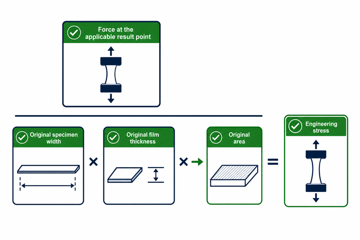
Plastic film tensile strength is the method-defined strength-point force divided by the specimen’s original cross-sectional area. For a rectangular specimen, the original area is equal to the original width multiplied by the original thickness. Each of these quantities is expressed in the same system of units, and the units of the final answer are units of force per area: N/mm² or MPa.
| Symbol | Meaning | Use in the calculation |
|---|---|---|
| F | Force at the applicable result point | N |
| w | Original specimen width | mm |
| t | Original film thickness | mm |
| A₀ | Original area, w × t | mm² |
| σ | Engineering stress at the named result point | N/mm² or MPa |
The NIST Guide to the SI states that the pascal is the SI unit of measure for pressure and stress. It’s expressed as force divided by area. Because 1 mm² is 10 −6 m², one newton per square millimetre is one megapascal.
Calculation boundary: tensile tester load and plastic deformation
Tensile force is the applied load. To determine tensile strength, stress at break, or stress at yield, divide the method-defined force at that result point by the original area.
Choose the Tensile Result Before You Calculate
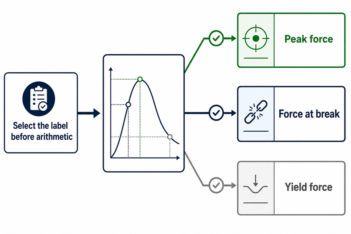
The correct force is the force at the result point as defined in the relevant test method, purchasing specification, or report format. It’s important to select the appropriate label before performing any calculations. Maximum force, force at break, and yield force can occur at different places on a stress-strain curve, so the label must be selected before arithmetic begins.
- Peak force: define the property as maximum-force tensile strength and use the procedure for that property.
- Force at break: where a method specifies using the tensile stress or strength at break of the material.
- Yield force: to be used when the governing method and the curve define a point of yield.
A thin plastic film undergoes continued deformation when stretched beyond the point of maximum tensile force and before rupture. If a worksheet silently substitutes break force for the curve peak, the division can be flawless while the reported tensile result is wrong.
Do not rename the curve: tensile modulus, yield strength, and elongation at break
Yield strength is the amount of stress that permanently changes the shape of a material. Maximum stress is the greatest stress a material can experience before failing. Tensile modulus is the ratio of stress to strain in the elastic region. The strain at break is the amount of strain a material can endure before failing. Each of these definitions is tied to its own property and test parameters; elongation and elongation at break are separate mechanical properties. The yield point and maximum stress are determined from a stress-strain curve.
Collect Force, Width, and Thickness
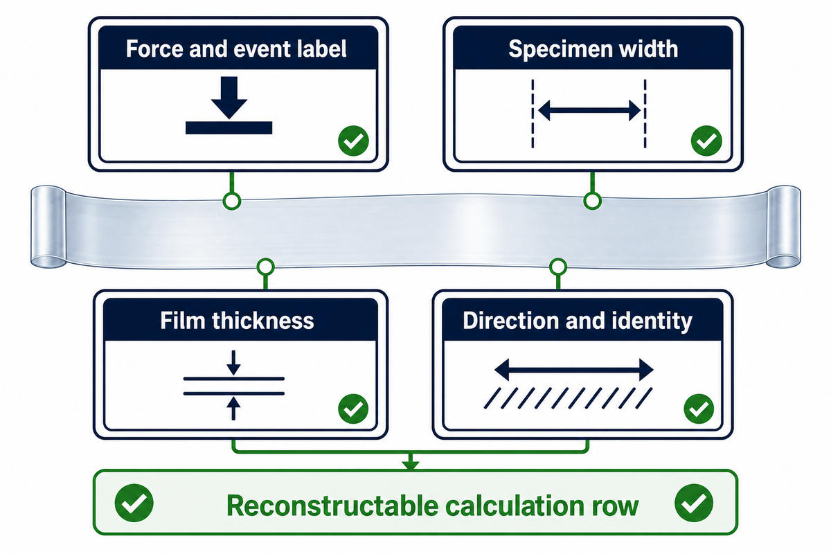
A calculation row needs the method-defined force, the tested specimen’s original width, and its original thickness. The same row should identify the film specimen, machine direction or transverse direction, sample or roll, measurement basis, and units before the numbers are combined. The quantities and their units are to be provided before any values are combined.
| Input | Record from | Reject or clarify when |
|---|---|---|
| Force and event label | Tensile testing machine and tensile test record | Only a force value is shown |
| Specimen width | Prepared strip measurement | Nominal cutter setting replaces measurement |
| Film thickness | Stated specimen measurement basis | A roll label is used without linkage |
| Direction and identity | Specimen preparation log | MD, TD, lot, or roll is missing |
Thickness appears in the denominator, so a nominal gauge can shift the result even when force and specimen width are correct. A peer-reviewed thin-film thickness measurement study shows why measurement capability and uncertainty matter at micrometre scale.
Practical record rule: thin plastic film specimen width and quality control
Store each value with its corresponding source. This prevents a measured force from being paired later with a nominal width or thickness from another specimen basis.
Convert Units Without a 1,000× Error
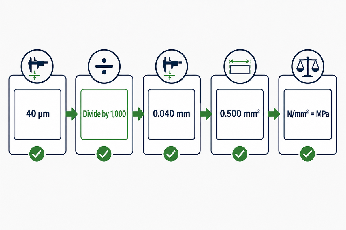
Calculate in millimetres. Convert thickness from micrometres to millimetres by dividing by 1,000, keep width in millimetres, and keep force in newtons. The result is N/mm², and no further numerical conversion is needed because N/mm² and MPa are equivalent.
Thickness: 40 µm ÷ 1,000 = 0.040 mm
Area: width in mm × thickness in mm = mm²
Stress: force in N ÷ area in mm² = N/mm² = MPa
Don’t multiply a millimetre width by a thickness that’s still in micrometres. Also check whether test equipment exports force in N or kN, because 0.0475 kN and 47.5 N are equal but 47.5 kN isn’t.
Wrong versus right
Wrong: 12.5 mm × 40 µm = 500 mm²
Right: 12.5 mm × 0.040 mm = 0.500 mm²
Plastic Film Tensile Strength Worked Example
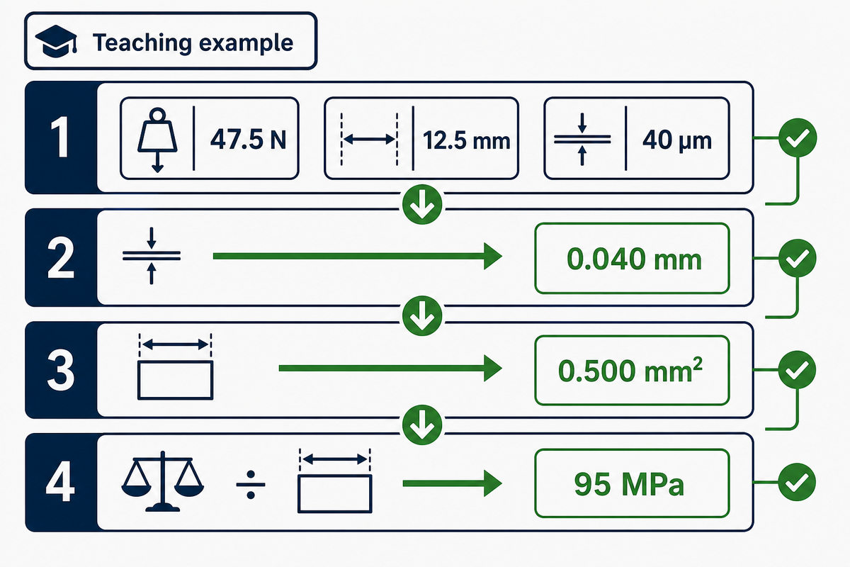
For this teaching example, the applicable method-defined maximum-force result is 47.5 N, the original specimen width is 12.5 mm, and thickness is 40 µm. Converting thickness to 0.040 mm gives 0.500 mm² original area and a calculated tensile strength of 95 MPa.
Worked calculation
1. t = 40 µm ÷ 1,000 = 0.040 mm
2. A₀ = 12.5 mm × 0.040 mm = 0.500 mm²
3. σ = 47.5 N ÷ 0.500 mm² = 95 N/mm²
4. Tensile strength = 95 MPa
The 47.5 N value is the method-defined maximum-force point in this teaching example, not a freely chosen point on the stress-strain curve. As used here, this definition pertains to the maximum-load event described in a tensile testing procedure. In other words, using a different tensile load in an experimental setup would not necessarily produce the method-defined material result.
| Thickness | Original area | Calculated stress | Interpretation |
|---|---|---|---|
| 38 µm | 0.475 mm² | 100 MPa | Same force, smaller denominator |
| 40 µm | 0.500 mm² | 95 MPa | Worked-example basis |
| 42 µm | 0.525 mm² | 90.5 MPa | Same force, larger denominator |
This table changes thickness only, so it shows sensitivity rather than full uncertainty. A defensible uncertainty statement also considers force, width, thickness, their measurement chains, and any relevant covariance; the National Physical Laboratory uncertainty guide explains the broader measurement approach.
Example status
The figures above are transparent teaching values. They are not a certificate value, acceptance limit, resin-family range, or performance claim for UD Packaging film.
The figures above are transparent teaching values. They are not a certificate value, acceptance limit, resin-family range, or performance claim for UD Packaging film.
Use the Three-Input Film Stress Check
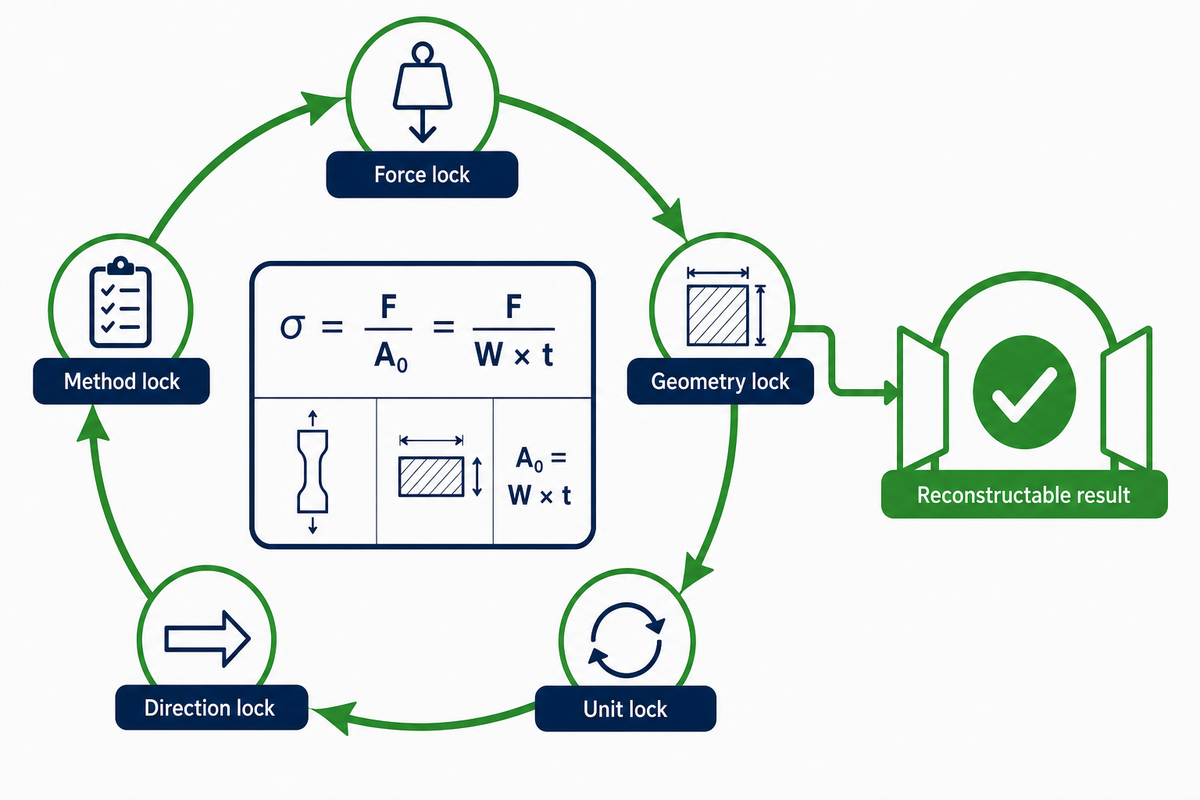
This five-step check ensures correct meaning isn’t carried by arithmetic. It verifies the force event, initial or original geometry, units and sense of direction, as well as the method or approach being taken. The stresses computed are accepted only as reconstructable calculation results after this check, not as material or package approval. This check is performed to validate reports to be issued or when comparing suppliers.
Three-Input Film Stress Check: film test setup, specimen preparation, test speed, and pneumatic grips
A five-lock audit for force, original geometry, units, specimen direction, and method context.
- Force lock: name the event as maximum, break, or yield and retain the machine record.
- Geometry lock: Record the original specimen width and the declared thickness basis.
- Unit lock: convert force and both dimensions before division.
- Direction Lock: Locks MD and TD on separate result lines.
- Method lock: maintain method edition, test speed, conditioning, pneumatic grips or other grip type, strain route, and exception notes.
This check is an editorial calculation aid, not a new testing standard. New standards for testing have not been set. Specimen preparation rules and requirements for calibration, quality control, and acceptance remain unchanged, along with those set in the governing ASTM D882 test, the ISO test, customer specification and material specification.
Pass or clarify: tensile testing of thin plastic film materials
Accept the completed check only when all five locks identify a reconstructable result. For comparative testing, resolve ambiguous data before combining results from different lots, suppliers, test laboratories, or machine settings.
When the Calculation Is Right but the Result Is Not Comparable
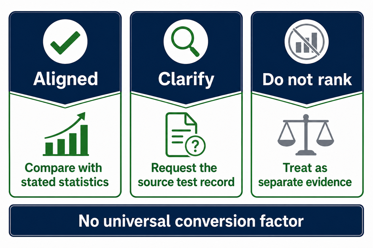
For comparative readiness, MPa results from different test procedures must be aligned with respect to the material and specimen, methodology and conditioning, test speed, test fixturing, gauge length and extension, failure mode, and other pertinent factors before ranking suppliers or accepting a value.
“This document specifies the conditions for determining the tensile properties of plastic films or sheets less than 1 mm thick.”
ISO 527-3:2018 public scope
The official ISO 527-3:2018 record says the edition was confirmed in 2024 and remains current. It describes test conditions for sheets and films less than 1 mm thick. It applies to films and sheets below 1 mm, uses ISO 527-1 for definitions and general principles, and is not normally suitable for cellular materials or plastics reinforced by textile fibres.
| Comparison state | Evidence condition | Action |
|---|---|---|
| Aligned | Method, definition, geometry, direction, conditions, and valid failure match | Compare with stated statistics |
| Clarify | One or more report fields are missing | Request the source test record |
| Do not rank | Result point, method route, direction, or failure validity differs | Treat as separate evidence |
The public ASTM D882-26 record identifies the active thin-plastic-sheeting method, but a shared material class does not make ASTM D882 and ISO 527-3 technically interchangeable. Never apply a universal conversion factor solely because both reports use MPa.
Failure boundary: ASTM standards, grip failure, and official standard scope
Investigate conditions such as slip in the grip, jaw misalignment, irregularities in the extension force/load trace, specimen edge damage, or defects prior to accepting or rejecting a test. The maximum tensile strength value does not justify acceptance of a specimen test.
Move the Number Into a Supplier Test Report
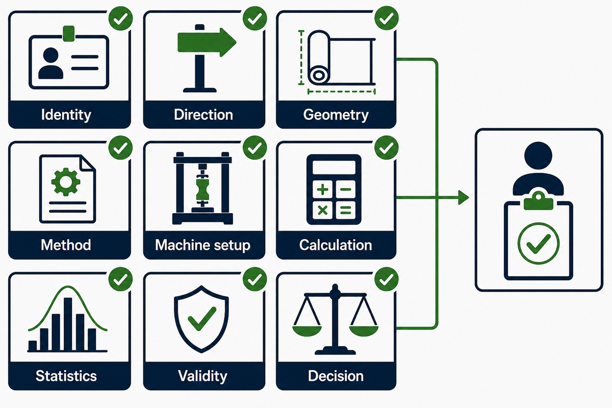
Test report information should enable a qualified user to reconstruct the test method and identify the test limitations. The test results must travel with specimen identity, direction, method edition, conditioning and settings, result-point label, original geometry, replicate summary, failure notes, deviations, and acceptance rule.
| Report field type | Minimum handoff fields | Why it matters | Limitations / Not suitable for |
|---|---|---|---|
| Identity | Material, lot, roll, and film specimen | Stops cross-sample mixing | Cannot replace material traceability |
| Direction | MD or TD for every result row | Preserves anisotropy context | Do not merge axes into one value |
| Geometry | Original width, thickness, and measurement basis | Defines original area | Nominal roll gauge alone is insufficient |
| Method | Standard, edition, conditioning, and test speed | Preserves the test route | No universal ASTM/ISO conversion |
| Machine setup | Grip, extension route, load range, and configured units | Exposes setup differences | Does not prove calibration status |
| Calculation | Force event, area, raw result, rounding, and unit | Makes arithmetic auditable | Cannot repair the wrong event label |
| Statistics | Specimen count, individual values, mean, and spread metric | Shows observed variation | A mean must not hide exclusions |
| Validity | Failure location, slip, edge damage, deviations, and uncertainty context | Flags questionable events | Not a substitute for method criteria |
| Decision | Acceptance rule, decision owner, and disposition | Separates evidence from approval | Not transferable to unrelated uses |
The NIST metrological traceability policy explains why a measurement result needs an unbroken comparison chain and stated uncertainty. Traceability supports confidence in the measurement basis, but it doesn’t prove that the chosen film test or acceptance limit fits a specific package.
Handoff test: repeatable test records and reliable test results
Give the report to a reviewer who did not run the test. A test report should be final when the user of the report is able to identify the tested specimen, and justify and explain the arithmetic and the result obtained.
What Tensile Strength Cannot Prove
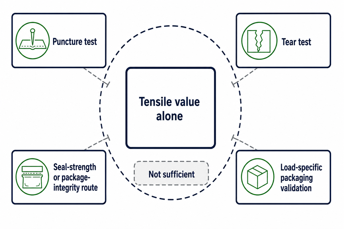
Tensile strength is a measured property of a material. Tensile strength of a laminated or multilayer structure doesn’t ensure or justify acceptance of the package seal, barrier film integrity, or package tear strength or show whether a finished package will withstand distribution loads.
| Buyer question | Evidence family | Tensile value alone |
|---|---|---|
| Will a sharp edge puncture the film? | Puncture test | Not sufficient |
| Will a nick propagate? | Tear test | Not sufficient |
| Will a heat seal open? | Seal-strength or package-integrity route | Not sufficient |
| Will a pallet load remain stable? | Load-specific packaging validation | Not sufficient |
Represent tensile data as one item in a property map and evaluate the additional plastic film testing guides and report elements to guide the final judgment. Unrelated materials or packages may exhibit behavior that is not established by the tensile-strength values indicated in the property map.
UD Packaging’s role
UD Packaging’s supplied company information does not establish an accredited laboratory or universal testing capability for materials. Therefore, information provided by UD Packaging for this guide does not determine material compliance with any test or specification; use the relevant property-specific or package-level validation.
UD Packaging’s supplied company information does not establish an accredited laboratory or universal testing capability for materials. Therefore, information provided by UD Packaging for this guide does not determine material compliance with any test or specification; use the relevant property-specific or package-level validation.
When not to use a tensile result as an acceptance decision
When assessing film for use in packaging, numerous performance characteristics may matter, including puncture, tear, sealing, barrier, friction, and stability. In the absence of the original geometry, or if the force event and specimen direction are not known, comparison of tensile results from different method routes is not valid without engineering review.
- Film of nominal thickness should be tested, and the reported thickness should be linked to that tested strip. If the tested film does not match the nominal thickness, do not accept the nominal value without clarifying its linkage to the tested strip.
- Film that exhibits grip break, slip, edge damage, or other defects should be described. Test reports should not be accepted as complete if defects in film or other irregularities are not reported for engineering review.
- Combining MD and TD should be avoided. If either MD or TD is not reported, comparison of the specimen axes should be avoided.
- If product failure warrants testing, the test should be selected for the specific failure risk rather than treating tensile strength as validation of the packaging.
Frequently Asked Questions
How Is Strength Expressed After Dividing the Maximum Force?
View answer
When the applicable result point is the method-defined curve peak, the calculation gives mechanical stress by dividing that force by the specimen’s original width multiplied by its original thickness. Strength is expressed as N/mm², numerically equal to MPa, when force is in newtons and both dimensions are in millimetres. Label the force as maximum, break, or yield, and keep the method edition and specimen direction with the value so the calculation can be interpreted later by another reviewer.
Is N/mm² the same as MPa?
View answer
Yes. One newton per square millimetre is numerically equal to one megapascal. Convert thickness before calculating area: divide micrometres by 1,000 to get millimetres, multiply width in millimetres by thickness in millimetres, and then divide force in newtons by that area. No extra numerical conversion is needed after N/mm² is obtained, but the result label still needs its method context.
Should a Film Tensile Test Use Peak Force or Force at Break?
View answer
A film tensile test uses a universal testing machine to record the force applied to test specimens at the result point required by the governing method, specification, or report definition. The curve peak supports a maximum-force result, while force at break supports a break result. They can coincide, but they are not interchangeable by default; a yield result is separate and needs a defensible curve definition. If the force event is missing, request the source curve or machine record before naming the result.
Why Do Test Specimens and Film Thickness Change the Tensile Properties of Thin Plastic?
View answer
For test specimens cut from film, thickness is part of the original area used to calculate stress. At the same force and width, a smaller thickness produces a higher calculated stress and a larger thickness produces a lower value. Record the measurement basis instead of silently relying on nominal roll gauge.
Do MD and TD need separate tensile results?
View answer
Yes, when film processing creates anisotropy or the specification requires both axes. Machine direction and transverse direction are different specimen orientations, so keep them on separate rows and do not infer one result from the other.
Can an ASTM D882 and ISO 527-3 Film Tensile Strength Test Be Converted?
View answer
Do not apply a universal conversion solely because both methods report stress. Compare the exact testing standard and method edition, specimen geometry, direction, conditioning, test speed, extension route, result definition, and failure validity before deciding whether two values answer the same question.
References & Sources
- ASTM D882-26 public standard record ASTM International
- ISO 527-3:2018 public scope and lifecycle record International Organization for Standardization
- NIST Guide to the SI: Pressure and Stress National Institute of Standards and Technology
- Metrological Traceability Policy National Institute of Standards and Technology
- Estimating Uncertainties in Testing National Physical Laboratory
- Thin-Film Thickness Measurement Study Applied Sciences
- Make It and Break It: Tensile Testing Activity University of Minnesota College of Science and Engineering
Film Specification Review
Reports of product test and construction should be provided, including width, thickness, roll details, intended use, and the available test report.